Connecting an HxC Floppy Emulator to an ST: Difference between revisions
No edit summary |
(Cleaned up formatting, re-added titles and indented Methods 1 and 2 for clarity) |
||
| (11 intermediate revisions by the same user not shown) | |||
| Line 1: | Line 1: | ||
| − | The HxC is a great piece of kit. It will allow Atari users to run software/games straight from disk 'images' with no need to rely on legacy floppy drives that are fast diminishing through failures. |
+ | The HxC Floppy Emulator is a great piece of kit to replace or use alongside your original floppy drive. It will allow Atari users to run software/games straight from disk 'images' with no need to rely on legacy floppy drives that are fast diminishing through failures. Once those legacy drives are all gone, that's your lot! |
| − | For owners of the HxC, the conundrum is how best to use it. The Atari will not boot from Drive B (DS1) and most people would like the flexibility of retaining the internal drive for legacy floppy support (or aesthetic reasons). Also, If you own several machines (ST, Falcon, Amiga, PC, Mac etc), it would be nice to be able to hook the HxC up to any of them as required. |
||
| + | ==Using HxC as a replacement for the internal floppy drive== |
||
| − | This solution provides a means to use the HxC as an external peripheral and attach it to the external drive port on an ST. A small modification inside the ST will provide the ability to swap the internal and external drive ID's around by the flick of a switch so you may boot from either source (See [[Drive Select Swap Mod]]) |
||
| + | Info to be added |
||
| − | == Tools you will need == |
||
| − | Phillips Screwdrivers |
||
| + | ==Using HxC as an external drive whilst still retaining the original internal floppy drive == |
||
| − | Soldering iron |
||
| + | === Method 1: an intermediate connector on a homemade enclosure === |
||
| − | Solder |
||
| + | This solution provides a means to use the HxC as an external peripheral and attach it to the external drive port on an ST. This method also provides the flexibility to hook your HxC up to other machines (ST, Falcon, Amiga, PC, Mac etc) simply by changing the peripheral cable. |
||
| − | Vacuum Pump |
||
| + | ==== Tools you will need ==== |
||
| − | Heat Shrink (Optional) |
||
| + | * Phillips Screwdrivers |
||
| − | Small electronics-style side cutters |
||
| + | * Soldering iron |
||
| + | * Solder |
||
| + | * Heat Shrink (Optional) |
||
| + | * Small electronics-style side cutters |
||
| + | * ESD protection |
||
| + | * Drill or handheld hobby tool |
||
| + | * Helping Hands (Optional) |
||
| + | * Goggles |
||
| + | * Gloves |
||
| + | * Face Mask |
||
| + | ==== Parts list ==== |
||
| − | ESD protection |
||
| + | * Project Case - I used Maplin product code: LF11 |
||
| − | Drill or handheld hobby tool |
||
| + | * 14-Way Male DIN plug and 14way data cable - I ordered a ready made cable from 16/32 (http://sales1632.myzen.co.uk/acatalog/Atari_Cables.html) |
||
| + | * 15-Way Male connector - I used a 2-row type so as not to confuse it with VGA |
||
| + | * 15-way female connector |
||
| + | * USB-B chassis mount connector |
||
| + | * Veroboard |
||
| + | * 34-way IDC flat floppy cable |
||
| + | ---- |
||
| − | Helping Hands (Optional) |
||
| + | ==== Part 1 - Drive select mod==== |
||
| − | IC extraction tool (if your sound chip is socket mounted) |
||
| + | Since the Atari will not natively boot from Drive B (DS1) a small modification inside the ST will need to be made first to add the ability to swap the internal and external drive ID's using a switch mounted on the rear of the machine so you can choose to boot from either source (See [[Drive Select Swap Mod]]) |
||
| − | Goggles |
||
| + | ==== Part 2 - Mounting the HxC into a case and making the intermediate connector==== |
||
| − | Gloves |
||
| − | |||
| − | Face Mask |
||
| − | |||
| − | |||
| − | == Parts list == |
||
| − | |||
| − | Project Case - I used Maplin product code: LF11 |
||
| − | |||
| − | 14-Way Male DIN plug and 14way data cable - I ordered a ready made cable from 16/32 (http://sales1632.myzen.co.uk/acatalog/Atari_Cables.html) |
||
| − | |||
| − | 15-Way Male connector - I used a 2-row type so as not to confuse it with VGA |
||
| − | |||
| − | 15-way female connector |
||
| − | |||
| − | USB-B chassis mount connector |
||
| − | |||
| − | Veroboard |
||
| − | |||
| − | 34-way IDC flat floppy cable |
||
| − | |||
| − | ---- |
||
| − | |||
| − | == Mounting the HxC into a case == |
||
1. Desolder the USB connector and LED's from the board and replace the USB connector with a small run of USB cable (I have used a USB-A to USB-B coupler on my chassis. Consequently I have used a USB-A connector on a short run of cable): |
1. Desolder the USB connector and LED's from the board and replace the USB connector with a small run of USB cable (I have used a USB-A to USB-B coupler on my chassis. Consequently I have used a USB-A connector on a short run of cable): |
||
[[File:HxC_without_LEDs_and_USB_Socket.jpg]] |
[[File:HxC_without_LEDs_and_USB_Socket.jpg]] |
||
| − | |||
| − | |||
2. Remount the LEDs onto a small piece of veroboard - bridge all the '''positive''' connectors together: |
2. Remount the LEDs onto a small piece of veroboard - bridge all the '''positive''' connectors together: |
||
[[File:HxC_casing_-_LED_Array.jpg]] |
[[File:HxC_casing_-_LED_Array.jpg]] |
||
| − | |||
| − | |||
3. Cut all the necessary holes in the chassis for the LED array, USB socket and 15-way male DSUB. |
3. Cut all the necessary holes in the chassis for the LED array, USB socket and 15-way male DSUB. |
||
| − | |||
| − | |||
4. Wire up the LED array to the HxC board as shown here: |
4. Wire up the LED array to the HxC board as shown here: |
||
| Line 74: | Line 59: | ||
[[File:HxC_LED_Array_rewired.jpg]] |
[[File:HxC_LED_Array_rewired.jpg]] |
||
| + | 5. Wire up the 34-way flat cable to the 15way DSUB to make the intermediate connector (Using all these lines means you can use the HxC on non-atari hardware also): |
||
| + | <pre>34w - 15w |
||
| − | |||
| − | 5. Wire up the 34-way flat cable to the 15way DSUB (Using all these lines means you can use the HxC on non-atari hardware also): |
||
| − | |||
| − | 34w - 15w |
||
2 ------ 1 |
2 ------ 1 |
||
| − | |||
8 ------ 9 |
8 ------ 9 |
||
| − | |||
10 ---- 2 |
10 ---- 2 |
||
| − | |||
12 ---- 10 |
12 ---- 10 |
||
| − | |||
14 ---- 3 |
14 ---- 3 |
||
| − | |||
16 ---- 11 |
16 ---- 11 |
||
| − | |||
18 ---- 4 |
18 ---- 4 |
||
| − | |||
20 ---- 12 |
20 ---- 12 |
||
| − | |||
22 ---- 5 |
22 ---- 5 |
||
| − | |||
24 ---- 13 |
24 ---- 13 |
||
| − | |||
26 ---- 6 |
26 ---- 6 |
||
| − | |||
28 ---- 14 |
28 ---- 14 |
||
| − | |||
30 ---- 7 |
30 ---- 7 |
||
| − | |||
32 ---- 15 |
32 ---- 15 |
||
| − | |||
34 ---- 8 |
34 ---- 8 |
||
ANY ODD LINE - Shielding (see my pic - the one with the heat-shrink around it) |
ANY ODD LINE - Shielding (see my pic - the one with the heat-shrink around it) |
||
| + | </pre> |
||
[[File:HxC_34Way_-_15Way_DSUB.jpg]] |
[[File:HxC_34Way_-_15Way_DSUB.jpg]] |
||
| − | |||
| − | |||
6. Finished assembly: |
6. Finished assembly: |
||
| Line 124: | Line 92: | ||
[[File:External_HxC_-_Complete-Back.jpg]] |
[[File:External_HxC_-_Complete-Back.jpg]] |
||
| + | ==== Part 3 - Making the Peripheral Cable ==== |
||
| − | ---- |
||
| − | |||
| − | == Peripheral Cable == |
||
Finally, here's how to make the cable for your new peripheral: |
Finally, here's how to make the cable for your new peripheral: |
||
| + | <pre> |
||
15w DSUB --- 14w DIN |
15w DSUB --- 14w DIN |
||
1 -------------- NC |
1 -------------- NC |
||
| − | |||
2 -------------- 5 |
2 -------------- 5 |
||
| − | |||
3 -------------- NC |
3 -------------- NC |
||
| − | |||
4 -------------- 9 |
4 -------------- 9 |
||
| − | |||
5 -------------- 11 |
5 -------------- 11 |
||
| − | |||
6 -------------- 13 |
6 -------------- 13 |
||
| − | |||
7 -------------- 1 |
7 -------------- 1 |
||
| − | |||
8 -------------- NC |
8 -------------- NC |
||
| − | |||
9 -------------- 4 |
9 -------------- 4 |
||
| − | |||
10 ------------- 6 |
10 ------------- 6 |
||
| − | |||
11 ------------- 8 |
11 ------------- 8 |
||
| − | |||
12 ------------- 10 |
12 ------------- 10 |
||
| − | |||
13 ------------- 12 |
13 ------------- 12 |
||
| − | |||
14 ------------- 14 |
14 ------------- 14 |
||
| − | |||
15 ------------- 2 |
15 ------------- 2 |
||
| − | |||
SHIELD ----- 3 + 7 |
SHIELD ----- 3 + 7 |
||
| + | </pre> |
||
[[File:HxC_to_Atari_ST_Cable.jpg]] |
[[File:HxC_to_Atari_ST_Cable.jpg]] |
||
| + | ---- |
||
| − | Back to [[DIY Hardware or %22mods%22]] |
||
| + | |||
| + | ===Method 2: Connecting the ST to the HxC with a single cable=== |
||
| + | |||
| + | If you have bought one of the more recent cased HxC rev C drive emulators, or you want a simpler cable solution, you may want to connect the ST directly to the HxC with no intermediate connector. If you don't feel confident enough or can't be bothered to make this, contact [[User:Galax|Galax]] or someone else who has commented on the forum threads about about having a cable made. |
||
| + | |||
| + | ==== Parts list ==== |
||
| + | |||
| + | <pre>Qty | Digi Key # | Manufacturer # | Description |
||
| + | ----+---------- -+-------------------|------------------------------------------ |
||
| + | 1 | OR981-ND | Omron XG5M-3432-N | CONN DBL ROW SOCKETS 34POS AWG24 |
||
| + | 2 | OR943-ND | Omron XG5S-1701 | CONN SEMI-COVER 17POS FOR XG5M |
||
| + | 0.5 | | Atari ST male-male 14 pin DIN floppy cable |
||
| + | |||
| + | (You only need half a floppy cable, as you can cut it in half and use it to make two of these cables)</pre> |
||
| + | |||
| + | ==== Connector Pinout ==== |
||
| + | |||
| + | <pre>34 Way Connector on HxC = 14 Pin DIN Atari ST Floppy Connector |
||
| + | ------------------------ --------------------------------------- |
||
| + | 2 Density Select = |
||
| + | 4 Reserved = |
||
| + | 6 Reserved = |
||
| + | 8 Index = 4 Index Pulse (yellow) |
||
| + | 10 Motor Enable A = 8* Motor On (dkbrown*) |
||
| + | 12 Drive Sel B = 6 Drive 1 Select (purple) |
||
| + | 14 Drive Sel A = 5 Drive 0 Select (dkgreen) |
||
| + | 16 Motor Enable B = 8* Motor On (dkbrown*) |
||
| + | 18 Direction = 9 Direction In (orange) |
||
| + | 20 Step = 10 Step (grey) |
||
| + | 22 Write Data = 11 Write Data (pink) |
||
| + | 24 Floppy Write Enable = 12 write gate (ltblue) |
||
| + | 26 Track 0 = 13 Track 00 (ltbrown) |
||
| + | 28 Write Protect = 14 Write Protect (ltgreen) |
||
| + | 30 Read Data = 1 Read Data (red) |
||
| + | 32 Head Select = 2 Side 0 Select (white) |
||
| + | 34 Disk Change/Ready = |
||
| + | Any Odd Pins = 7 + 3 Logic Ground (black + dkblue) |
||
| + | |||
| + | * Both Motor Enable A and B are connected to the ST's Motor On (makes sense to me!) |
||
| + | </pre> |
||
| + | |||
| + | The colours refer to the wires in my ST floppy cable. No idea if these are universal, but it may speed up your continuity checking a bit! |
||
| + | |||
| + | I stripped and tinned the wires before pressing into the 34 way rectangular connector, because I was only prototyping it at first. You should be able to just crimp the insulated wire into the connector, which is quicker and easier. |
||
| + | |||
| + | A handy guide to the pin numbering of the ST's 14 pin floppy connector is here, remember that this numbering is of the socket on the ST as you look at it, so when you hold the plug of the cable facing towards you the numbering would be mirrored: [http://info-coach.fr/atari/hardware/interfaces.php#Floppy_Disc_Connector] |
||
| + | |||
| + | [[File:HXC_Floppy_connector_close.jpg]] [[File:HXC_Floppy_connector_far.jpg]] |
||
| + | |||
| + | ==== Jumper settings ==== |
||
| + | |||
| + | Jumper settings for HxC as both drives A and B. You can boot from the HxC's drive A in this mode. This works perfectly with an ST or STM, but the internal floppy drive should be unplugged with an STFM, STE, etc.: |
||
| + | |||
| + | [[File:HXC_Floppy_connector_AB.jpg]] |
||
| + | |||
| + | Jumper settings for HxC as external drive (HxC thinks it is 'A' which is the default on power up, ST sees it as 'B'. Only 1 jumper is connected, the one on the right is just half plugged in so I don't lose it): |
||
| + | |||
| + | [[File:HXC_Floppy_connector_B.jpg]] |
||
| + | |||
| + | ==== Power cable ==== |
||
| + | |||
| + | You'll also need a power cable, I connected the +5v and -ve pins from a recycled USB cable to an old connector that I adapted, would be easier to buy the correct adapter. |
||
| + | |||
| + | [[File:HXC_Floppy_connector_power.jpg]] |
||
| + | |||
| + | ---- |
||
| + | <br /> |
||
| + | <br /> |
||
| + | back to [[Hardware hacks]] |
||
| + | |||
| + | <br /> |
||
| + | <br /> |
||
| + | <br /> |
||
| + | [[Category:Hardware DIY]] |
||
Latest revision as of 16:14, 24 February 2016
The HxC Floppy Emulator is a great piece of kit to replace or use alongside your original floppy drive. It will allow Atari users to run software/games straight from disk 'images' with no need to rely on legacy floppy drives that are fast diminishing through failures. Once those legacy drives are all gone, that's your lot!
Using HxC as a replacement for the internal floppy drive
Info to be added
Using HxC as an external drive whilst still retaining the original internal floppy drive
Method 1: an intermediate connector on a homemade enclosure
This solution provides a means to use the HxC as an external peripheral and attach it to the external drive port on an ST. This method also provides the flexibility to hook your HxC up to other machines (ST, Falcon, Amiga, PC, Mac etc) simply by changing the peripheral cable.
Tools you will need
- Phillips Screwdrivers
- Soldering iron
- Solder
- Heat Shrink (Optional)
- Small electronics-style side cutters
- ESD protection
- Drill or handheld hobby tool
- Helping Hands (Optional)
- Goggles
- Gloves
- Face Mask
Parts list
- Project Case - I used Maplin product code: LF11
- 14-Way Male DIN plug and 14way data cable - I ordered a ready made cable from 16/32 (http://sales1632.myzen.co.uk/acatalog/Atari_Cables.html)
- 15-Way Male connector - I used a 2-row type so as not to confuse it with VGA
- 15-way female connector
- USB-B chassis mount connector
- Veroboard
- 34-way IDC flat floppy cable
Part 1 - Drive select mod
Since the Atari will not natively boot from Drive B (DS1) a small modification inside the ST will need to be made first to add the ability to swap the internal and external drive ID's using a switch mounted on the rear of the machine so you can choose to boot from either source (See Drive Select Swap Mod)
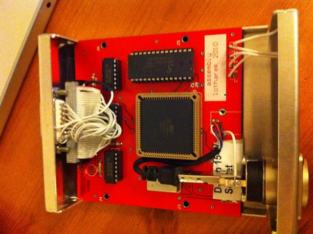
Part 2 - Mounting the HxC into a case and making the intermediate connector
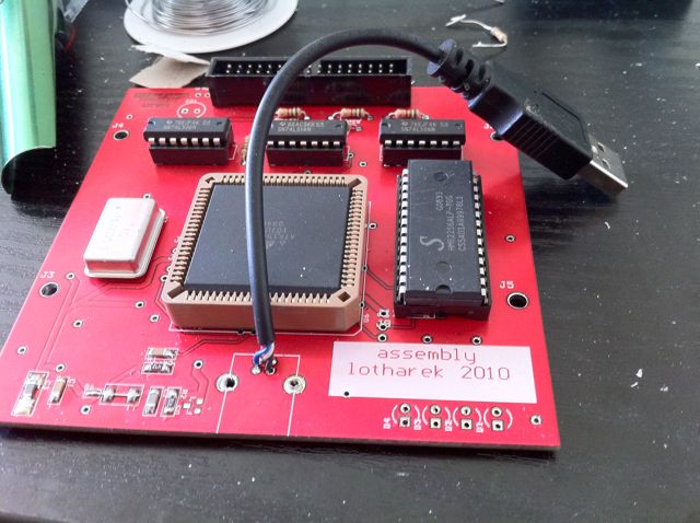
1. Desolder the USB connector and LED's from the board and replace the USB connector with a small run of USB cable (I have used a USB-A to USB-B coupler on my chassis. Consequently I have used a USB-A connector on a short run of cable):
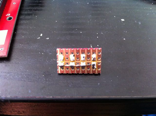
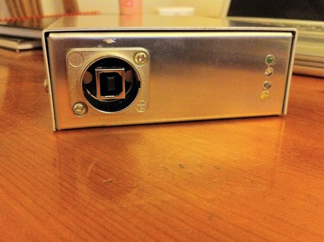
2. Remount the LEDs onto a small piece of veroboard - bridge all the positive connectors together:
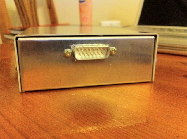
3. Cut all the necessary holes in the chassis for the LED array, USB socket and 15-way male DSUB.
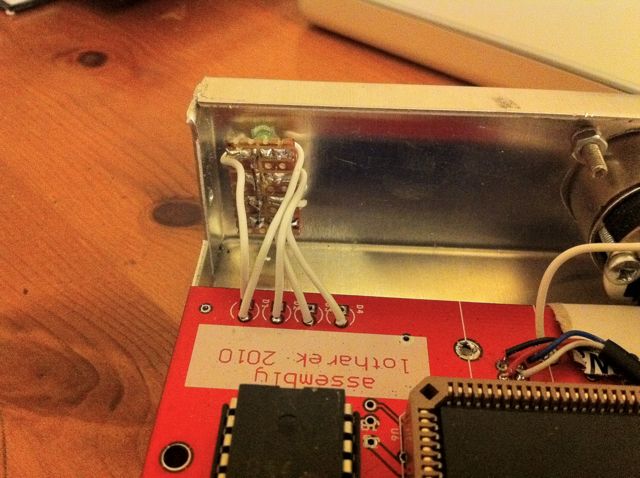
4. Wire up the LED array to the HxC board as shown here:
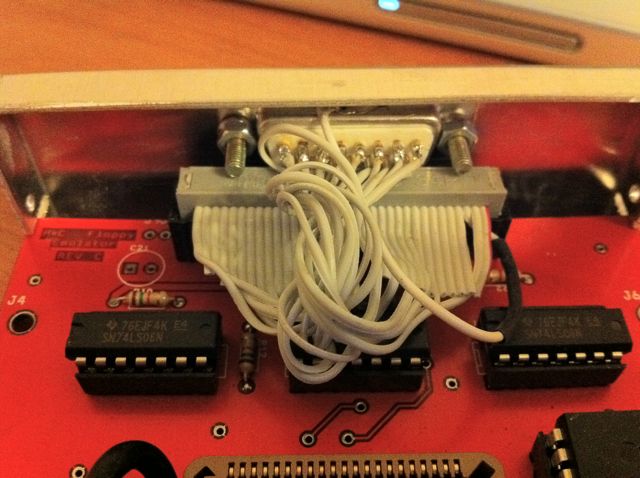
5. Wire up the 34-way flat cable to the 15way DSUB to make the intermediate connector (Using all these lines means you can use the HxC on non-atari hardware also):
34w - 15w

2  ------  1
8  ------  9
10 ---- 2
12 ---- 10
14 ---- 3
16 ---- 11
18 ---- 4
20 ---- 12
22 ---- 5
24 ---- 13
26 ---- 6
28 ---- 14
30 ---- 7
32 ---- 15
34 ---- 8

ANY ODD LINE - Shielding  (see my pic - the one with the heat-shrink around it)
6. Finished assembly:
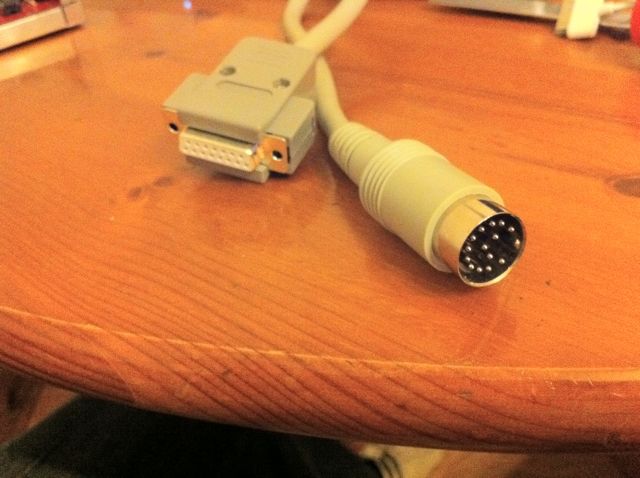
Part 3 - Making the Peripheral Cable
Finally, here's how to make the cable for your new peripheral:
15w DSUB --- 14w DIN

1 -------------- NC
2 -------------- 5
3 -------------- NC
4 -------------- 9
5 -------------- 11
6 -------------- 13
7 -------------- 1
8 -------------- NC
9 -------------- 4
10 ------------- 6
11 ------------- 8
12 ------------- 10
13 ------------- 12
14 ------------- 14
15 ------------- 2
SHIELD ----- 3 + 7
Method 2: Connecting the ST to the HxC with a single cable
If you have bought one of the more recent cased HxC rev C drive emulators, or you want a simpler cable solution, you may want to connect the ST directly to the HxC with no intermediate connector. If you don't feel confident enough or can't be bothered to make this, contact Galax or someone else who has commented on the forum threads about about having a cable made.
Parts list
Qty | Digi Key # | Manufacturer #    | Description
----+---------- -+-------------------|------------------------------------------
1   | OR981-ND   | Omron XG5M-3432-N | CONN DBL ROW SOCKETS 34POS AWG24
2   | OR943-ND   | Omron XG5S-1701   | CONN SEMI-COVER 17POS FOR XG5M
0.5 |                                | Atari ST male-male 14 pin DIN floppy cable

(You only need half a floppy cable, as you can cut it in half and use it to make two of these cables)
Connector Pinout
34 Way Connector on HxC  = 14 Pin DIN Atari ST Floppy Connector
------------------------   ---------------------------------------
2  Density Select        =
4  Reserved              =
6  Reserved              =
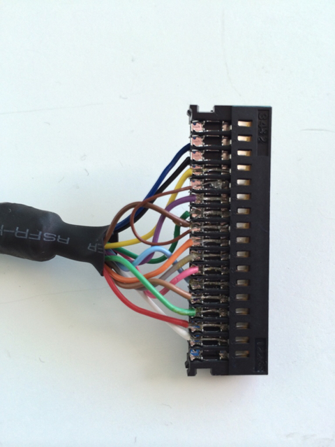
8  Index                 =  4     Index Pulse     (yellow)
10 Motor Enable A        =  8*    Motor On        (dkbrown*)
12 Drive Sel B           =  6     Drive 1 Select  (purple)
14 Drive Sel A           =  5     Drive 0 Select  (dkgreen)
16 Motor Enable B        =  8*    Motor On        (dkbrown*)
18 Direction             =  9     Direction In    (orange)
20 Step                  =  10    Step            (grey)
22 Write Data            =  11    Write Data      (pink)
24 Floppy Write Enable   =  12    write gate      (ltblue)
26 Track 0               =  13    Track 00        (ltbrown)
28 Write Protect         =  14    Write Protect   (ltgreen)
30 Read Data             =  1     Read Data       (red)
32 Head Select           =  2     Side 0 Select   (white)
34 Disk Change/Ready     =
Any Odd Pins             =  7 + 3 Logic Ground    (black + dkblue)

* Both Motor Enable A and B are connected to the ST's Motor On (makes sense to me!)
The colours refer to the wires in my ST floppy cable. No idea if these are universal, but it may speed up your continuity checking a bit!
I stripped and tinned the wires before pressing into the 34 way rectangular connector, because I was only prototyping it at first. You should be able to just crimp the insulated wire into the connector, which is quicker and easier.
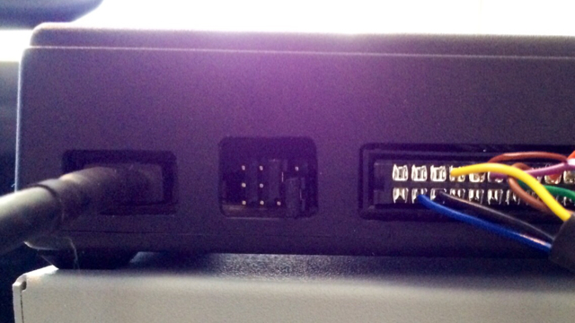
A handy guide to the pin numbering of the ST's 14 pin floppy connector is here, remember that this numbering is of the socket on the ST as you look at it, so when you hold the plug of the cable facing towards you the numbering would be mirrored: [1]
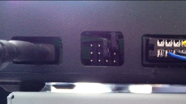
Jumper settings
Jumper settings for HxC as both drives A and B. You can boot from the HxC's drive A in this mode. This works perfectly with an ST or STM, but the internal floppy drive should be unplugged with an STFM, STE, etc.:
Jumper settings for HxC as external drive (HxC thinks it is 'A' which is the default on power up, ST sees it as 'B'. Only 1 jumper is connected, the one on the right is just half plugged in so I don't lose it):
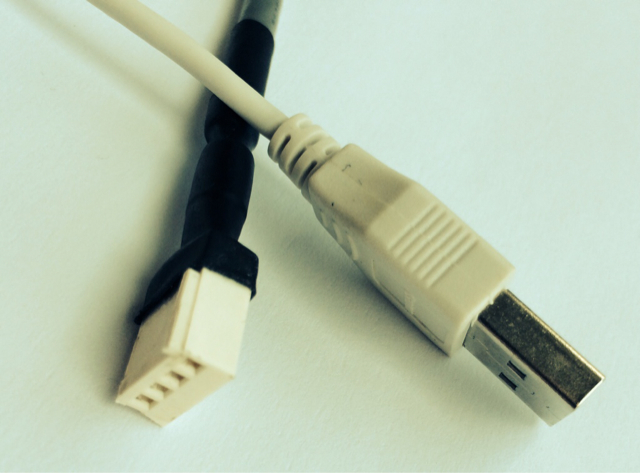
Power cable
You'll also need a power cable, I connected the +5v and -ve pins from a recycled USB cable to an old connector that I adapted, would be easier to buy the correct adapter.
back to Hardware hacks
