Nemesis
Nemesis accelerates the entire Falcon system by 50% therefore most software will run without modification. There are, however, some pitfalls to avoid.
In common with all system accelerators, Nemesis modifies the system clock. Since this clock supplies the 32MHz dot clock to the Videl chip this signal will be 32, 40 or 48MHz depending on the status of the Nemesis switches. Software which depends on the system clock being 32MHz, or requires a 32MHz dot clock to provide enhanced resolutions, will fail. Obviously this affects RGB users most because RGB resolutions use the 32MHz clock.
A switch has been provided on the Nemesis board to allow the 25MHz clock to be replaced with a 32MHz one. This allows the Falcon to be accelerated with an RGB monitor and still produce sensible video. For this reason it is inadvisable to change the dot clock when setting up the display using the hardware registers while running on an RGB monitor. Either retain the current dot clock or use Vsetmode to change resolution.
Avoid using instruction sequences to provide delay loops in timing critical code. Any FOR ... NEXT type construct will take 33% less time when Nemesis is running at 48MHz regardless of language. Use the MFP timers for accurate delays. This one applies to any accelerator.
That's it. Generally any software which is completely clean and doesn't set up it's display using the hardware registers will work perfectly well.
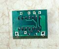
Nemesis Accelerator Photos
Nemesis Buffer Photos
Updates & Corrections to manual
PLEASE READ FIRST BEFORE INSTALLATION, ESPECIALLY POINTS 8.1 & 9.2
Installation tips
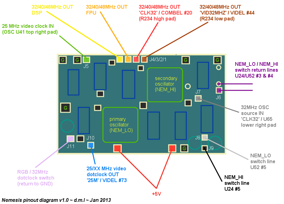
The stock Nemesis wires that come with the board are in the most part unsuitable for a stable installation as they provide no RF shielding which can can cause the board to perform unpredictably and in an unstable manner. It is recommended to replace the majority of the stock coloured wires with mini COAX cable and connect the shielding from each cable to the numerous 'e' points (same as 'G' points on diagram below) on the Nemesis board and the main ground that runs around the perimeter of the Falcon motherboard.
| Colour | Jumper Number | COAX Y/N | FUNCTION |
|---|---|---|---|
| Brown | J1 | Y | |
| Red | J2 | Y | |
| Orange | J3 | Y | |
| Yellow | J4 | Y | |
| Green | J5 | Y | |
| Purple | J6 | Y | |
| Grey | J7 | Y | |
| White | J8 | N | Nemesis board switching |
| Black | J9 | N | Nemesis board switching |
| Blue | J10 | Y | |
| Pink | J11 | N | Nemesis board switching |
| Red (thick wire) | +5V | N | Power |
| e | N | Ground |
Wiring Diagram
External Links
- Nemesis Installation Manual
- Nemesis Software
- Nemesis Indicator v2 - 3rd party software accessory for Nemesis & Phantom
- Atari Forum - Discussion thread 1
- Atari Forum - Discussion thread 2 (Wiring diagram and installtion by DML)
- Atari Forum - Discussion thread 3 (Detailed installation text guide by Simbo)
- Atari Forum - Discussion thread 4 (Stability issues)


