Drive Select Swap Mod
The Atari ST in unable to boot from an external floppy drive. Once implemented, this modification will provide a switch that swaps the drive select signals allowing the ablilty to toggle Drive A between the internal and external unit.
This is particularly useful if you have invested in a HxC floppy emulator and you would like the ability to have it externally connected to you ST and optionally boot from it.
Tools you will need
Phillips Screwdrivers
Soldering iron
Solder
Vacuum Pump
Heat Shrink (Optional)
Small electronics-style side cutters
ESD protection
Drill or handheld hobby tool
Helping Hands (Optional)
IC extraction tool (if your sound chip is socket mounted)
Parts list
DPDT switch
Wire
The DS0/DS1 signal mod inside the ST
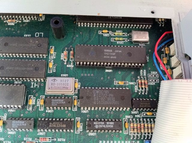
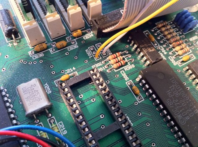
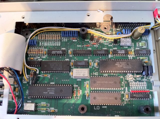
1. Open it all up and locate the Yamaha sound chip (U202 on STE):
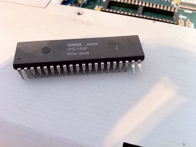
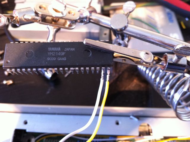
2. Mine is in a socket however you may not be so lucky - If yours is mounted, then you will need to cut the legs 19 and 20. I have extracted mine using an IC extraction tool and very gently bent the legs so they are sticking out:
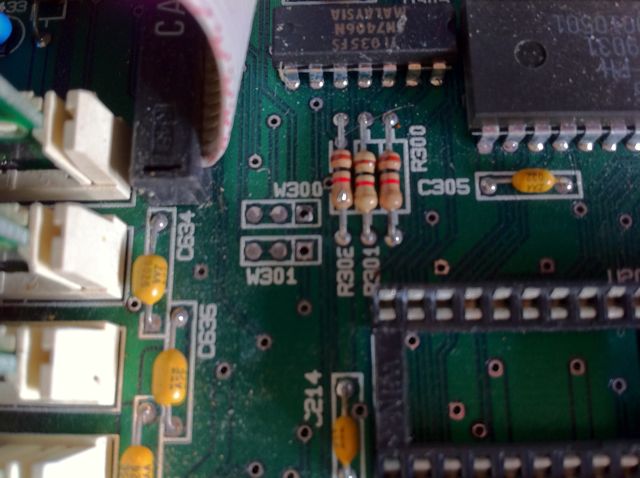
3. We now need a good line on the board for DS0 and DS1. These can be found at W301 (DS0) and W300 (DS1) handily located near the sound chip. Flip the board over and remove the solder from pin 1 at each of these points using a vacuum pump:
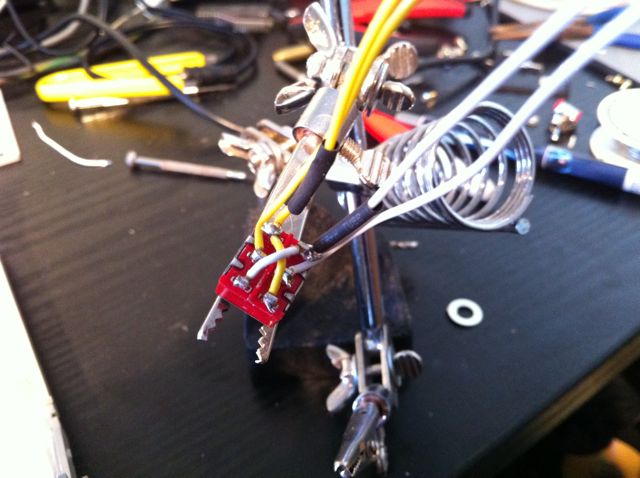
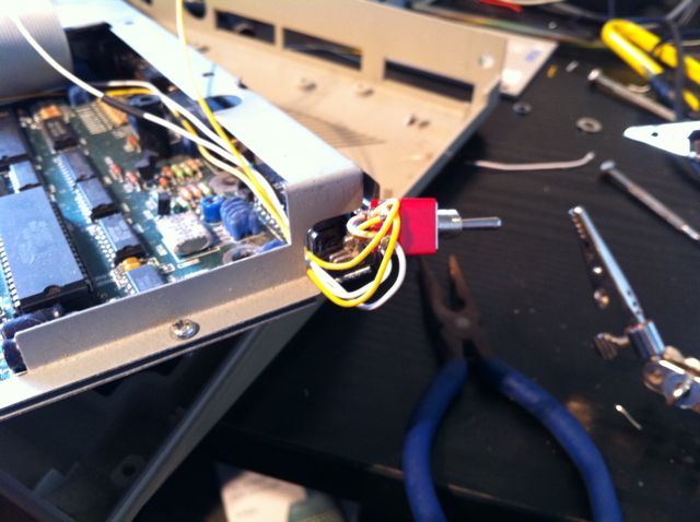
4. Now sort the switch out. You must use a DPDT switch! I have used Yellow wire for the DS0 line and White for DS1. Solder as shown, the middle pins will be going to W300 and W301 and the right pins will be going to the sound chip. run a piece of heat shrink sleeve down the lines destined for the chip, we will use them later and it serves as a reminder as to what lines go where:
5. Solder the wires coming from the centre pins of the switch to W301 (DS0 - Yellow Wire) and W300 (DS1 - White Wire). Solder from the underside of the board and make sure you cut the excess wire using a small pair of electronics side cutters as flush as possible to the solder joint:
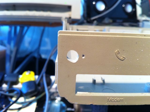
6. Make a hole for your switch:
7. Reassemble the shielding making sure you don't trap the wires anywhere, I used the gap near the serial port for this. You can now reassemble the bottom half of the ST and mount the switch:
8. Now solder the pins on the chip: Pin20=DS0 (Yellow wire) and Pin19=DS1 (White Wire):
9. Apply the heat shrink over the pins, re-seat the socket (if required) and route the wires as neat as you care to:
Proceed to Connecting an HxC Floppy Emulator to an ST
back to Hardware hacks
