Basic Troubleshooting - Logic probe basics
As tools go, the Logic Probe is likely one of the oldest you will find, and also one of the simplest. Modern devices are very inexpensive, but also a useful stepping stone before breaking out he big guns like oscilloscopes.
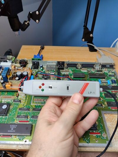
This is mine:
Some modern devices also include an audio tone to give you a clue about what is going on, but I find this distracting so I have a silent device which just shows logic levels.
In computers like the Atari ST and it's counterparts, TTL logic is used. This is akin to binary in that a 1 is represented by 5v and is known as 'High', and 0v is known as 'Low' and represents a binary 0. As you can see my probe has two LEDs, red for 1 or 'High' and green for 0 or 'Low'.
Since ware talking about computers, we know that a pin can change rapidly from 1 to 0, and this is difficult to measure with a multimeter. This is where a logic probe comes in, and the 3rd LED, 'Pulse' tells us about this rapidly changing state.
Note that my probe, and others that are available will likely have 2 other controls: Mem, which remembers the last state the probe measured, and CMOS/TTL. I never use Mem personally. Since computers of the era we are working on use TTL or 5v logic, then you should leave that switch at TTL.
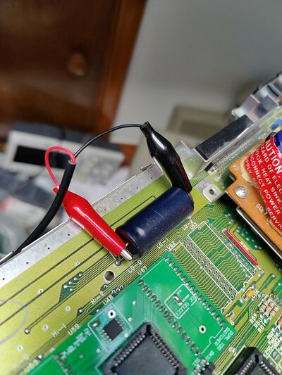
A logic probe requires power to work, and can be something as simple as connecting to either side of a capacitor like this:
But you may need to find alternative sources depending on just what area of the board you're working in and how long the power lead is. There is nothing stopping you from using a suitable external PSU to power the logic probe.
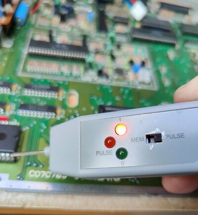
This is my probe showing High:
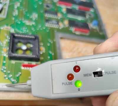
And Low:
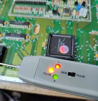
And here the ST is running as normal at the desktop, and I am touching the D5 data line of the CPU with the probe:
Here you can see both 1, 0 and Pulse illuminated, indicating that the D5 line at the changing rapidly between 1 and 0.
There are connections, such as the address and data lines that you would expect to do this, and you can gather data about these from the datasheet of the relevant part. Some pins, like the RESET and HALT pins of the 68000 are 'active low'.
This means that they will will be at 1, or 5v during normal operations, and when active will drop to 0 or 0v. These states can be tested with a logic probe, and if either RESET and HALT are probed whilst the reset button is pressed, you can see that state change happen before your eyes on the logic probe LEDs.
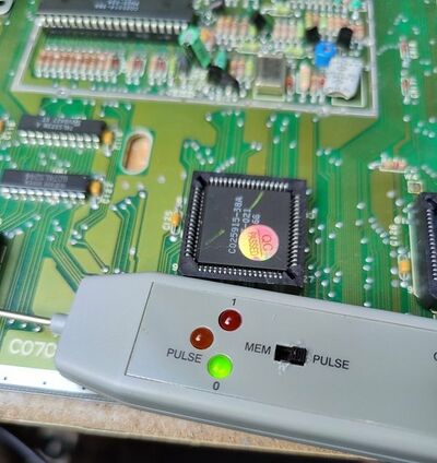
To indicate how useful the logic probe is, in this next image we can see the D5 pin of the 68000 CPU we looked at earlier and saw pulsing:
Here I have shorted 2 of the data lines briefly to cause the system to lock up, and in this case show 2 bombs on screen. Here we see that the pin is now held low, or 0.This is a good indicator that the CPU is doing nothing, and a check of the HALT pin might show it as low also.
So as you can see, a logic probe is a useful tool which can help us see the logic state of any of the pins on any of our chips at any time. If we can then relate these to a known working state and there is a difference, it can give us useful clues as to what may be causing us problems with our machine.
