Connecting an HxC Floppy Emulator to an ST
The HxC is a great piece of kit. It will allow Atari users to run software/games straight from disk 'images' with no need to rely on legacy floppy drives that are fast diminishing through failures. Once those legacy drives are all gone, that's your lot!
For owners of the HxC, the conundrum is how best to use it. The Atari will not boot from Drive B (DS1) and most people would like the flexibility of retaining the internal drive for legacy floppy support (or aesthetic reasons). Also, If you own several machines (ST, Falcon, Amiga, PC, Mac etc), it would be nice to be able to hook the HxC up to any of them as required.
This solution provides a means to use the HxC as an external peripheral and attach it to the external drive port on an ST. A small modification inside the ST will provide the ability to swap the internal and external drive ID's around by the flick of a switch so you may boot from either source (See Drive Select Swap Mod)
Tools you will need
Phillips Screwdrivers
Soldering iron
Solder
Vacuum Pump
Heat Shrink (Optional)
Small electronics-style side cutters
ESD protection
Drill or handheld hobby tool
Helping Hands (Optional)
IC extraction tool (if your sound chip is socket mounted)
Goggles
Gloves
Face Mask
Parts list
Project Case - I used Maplin product code: LF11
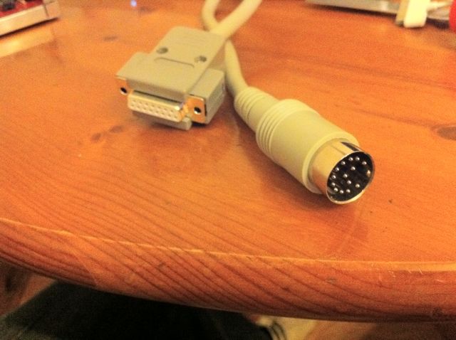
14-Way Male DIN plug and 14way data cable - I ordered a ready made cable from 16/32 (http://sales1632.myzen.co.uk/acatalog/Atari_Cables.html)
15-Way Male connector - I used a 2-row type so as not to confuse it with VGA
15-way female connector
USB-B chassis mount connector
Veroboard
34-way IDC flat floppy cable
Mounting the HxC into a case
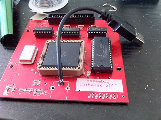
1. Desolder the USB connector and LED's from the board and replace the USB connector with a small run of USB cable (I have used a USB-A to USB-B coupler on my chassis. Consequently I have used a USB-A connector on a short run of cable):
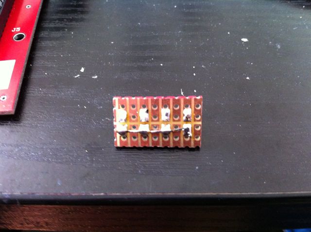
2. Remount the LEDs onto a small piece of veroboard - bridge all the positive connectors together:
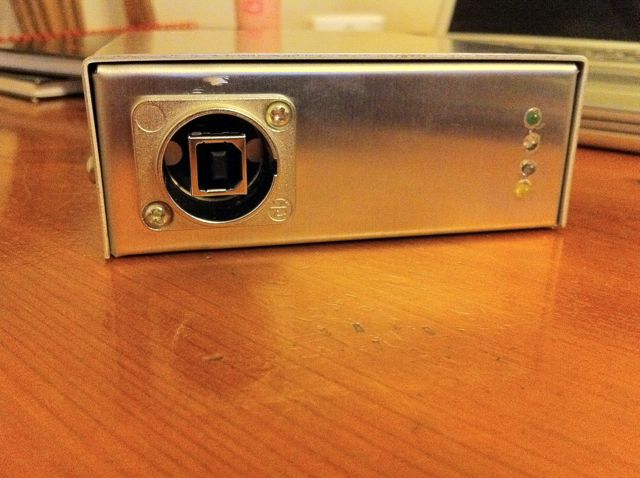
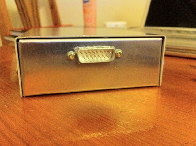
3. Cut all the necessary holes in the chassis for the LED array, USB socket and 15-way male DSUB.
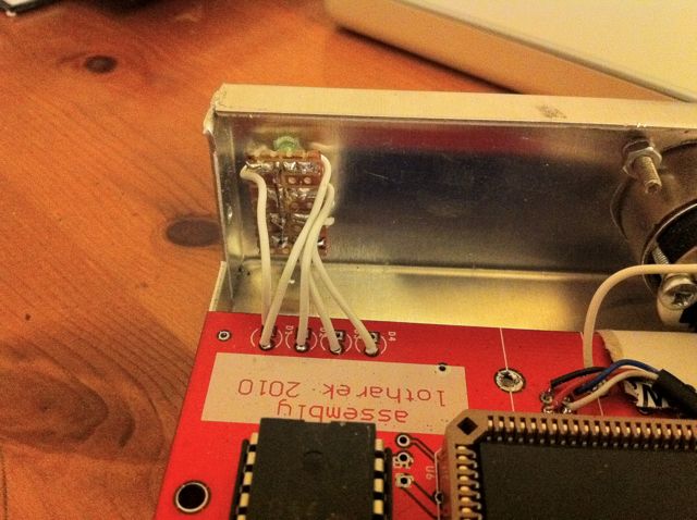
4. Wire up the LED array to the HxC board as shown here:
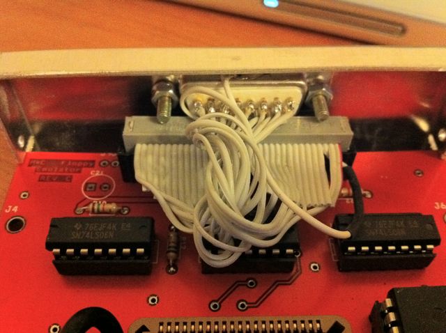
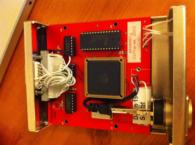
5. Wire up the 34-way flat cable to the 15way DSUB (Using all these lines means you can use the HxC on non-atari hardware also):
34w - 15w
2 ------ 1
8 ------ 9
10 ---- 2
12 ---- 10
14 ---- 3
16 ---- 11
18 ---- 4
20 ---- 12
22 ---- 5
24 ---- 13
26 ---- 6
28 ---- 14
30 ---- 7
32 ---- 15
34 ---- 8
ANY ODD LINE - Shielding (see my pic - the one with the heat-shrink around it)
6. Finished assembly:
Peripheral Cable
Finally, here's how to make the cable for your new peripheral:
15w DSUB --- 14w DIN
1 -------------- NC
2 -------------- 5
3 -------------- NC
4 -------------- 9
5 -------------- 11
6 -------------- 13
7 -------------- 1
8 -------------- NC
9 -------------- 4
10 ------------- 6
11 ------------- 8
12 ------------- 10
13 ------------- 12
14 ------------- 14
15 ------------- 2
SHIELD ----- 3 + 7
Back to DIY Hardware or "mods"
