Changing the TOS of an Atari (STF/STE/Mega)
Hello, here is a tutorial on updating the TOS of our machines. I imagine that for many of you, this will be familiar, but you never know.
Why change the TOS and with this FAQ?
Unlike modern PCs and Macs, on the ST, the operating system is stored in ROM chips on the motherboard (except for the very first ST models). The big advantage of this solution is that it allows for nearly instant startup and is quite resilient over the years. However, updating the system requires a hardware operation and the replacement of these chips with new ones. Over the years, Atari has evolved its OS, and different versions of TOS have been released, each bringing its share of new features (and incompatibilities). In addition to Atari's TOS, other versions have emerged, fixing bugs and modernising the OS.
Changing the TOS can be interesting for several reasons: having a more modern desktop, fixing bugs, being able to easily boot from an IDE drive or an UltraSatan, etc.
The purpose of this FAQ is to gather the necessary information for changing your TOS by yourself, but it does not go into the details of the TOS itself; there are plenty of excellent articles on that. There may be some shortcuts, likely errors, or missing information, so please don't hesitate to let me know.
Different TOS versions
There are several versions of TOS, from the 1.0 of the very first ST models to the 4.04 of the Falcon. Here are a few key advantages and disadvantages of versions 1.x and 2.x. Versions 3.x and 4.x, reserved for TTs and Falcons, are not covered here. As soon as someone gives me one of these machines, I will update the document 😀. I also won't discuss other OSes (Mint, MultiTOS, etc.) since they are not stored in ROM anyway.
TOS Compatibility

TOS Language
You can search everywhere in the menus, there is no option to change the language of your TOS. Each chip contains only one language, and to change it, you need to change your TOS. So if you want your beautiful Mega STE from Germany to speak in the language of Molière, you need to change the TOS. But be aware that the keyboard mapping also depends on the TOS, so if you put a French TOS into an English machine with a QWERTY keyboard, every press of Q will display a beautiful A as on an AZERTY keyboard. Fortunately, there are utilities to change the keyboard: Keyedit, CKBD, or Clocky.
Advantages and disadvantages of different TOS versions
- TOS 1.0 and TOS 1.02 : The first versions of TOS, considered the most "compatible" with most games. On the downside, there are quite a few small bugs, but more importantly, limited compatibility with hard drives. For example, it will be impossible to have partitions larger than 256MB, a limited number of files per directory, and so on.
TOS 1.02

- TOS 1.04: Also known as "Rainbow TOS," it fixes many bugs and allows for easy use of a hard drive but brings some incompatibilities with older games. This is generally not a problem as most games have long been patched to work with versions 1.4 or 2.06, but if you have original floppy disks, they may no longer work.

- TOS 1.06 and TOS 1.62: These are the first versions for STE and only work on STE. Version 1.06 is almost identical to TOS 1.04 but supports STE's new features, and 1.62 is just a bug fix for 1.06, with no major changes. However, 1.06 has a annoying bug, it doesn't save the resolution properly. So it's impossible to start in Medium resolution; you have to manually change it after booting. It's not a big deal but can be quite annoying. Utilities exist to fix this (STE_FIX.PRG to be placed in AUTO).
- TOS 2.02 and 2.05: The first TOS versions for Mega STE, quite rare.
- TOS 2.06 : This is the only version of TOS (by Atari) that works on all ST to Mega STE machines... almost. It brings a new desktop with many improvements, extended support for hard drives, and so on. Unfortunately, all of this comes at the expense of compatibility with older software, but once again, most have been patched long ago. However, please note that this version of TOS will not work on an ST, STF, or Mega ST without a hardware modification; we will come back to this.


Other TOS
There are several other TOS versions not produced by Atari that can be installed in your ST:
- EmuTOS: This is a complete rewrite of TOS, entirely open-source and having good compatibility. EmuTOS brings many new features, greatly improves disk management, and more. Note that if your machine has enough memory, it may not be necessary to install EmuTOS in ROM; it can be loaded from a floppy disk or the hard drive at boot. EmuTOS website
- Pera Putnik's TOS: Available on PPera's website, these are based on the original TOS but include many bug fixes and the ability to boot TOS 1.4 from an IDE drive, and more. Since they are based on the original TOS, compatibility is good, and there are even "chimera" versions like TOS 1.4 with the desktop of version 2.06 to have new features while maintaining maximum compatibility. PPera's TOS
- Others: I only know them by name (KaosTOS, SuperTOS, etc.) and therefore can't say much about them.
For those who want to delve deeper into TOS, I recommend the presentation by Vincent Rivière and Frédéric Sagez here.
Change your TOS
Before changing your TOS
Changing your TOS is, in most cases, a fairly simple operation. You just need to replace your chips with new ones containing the version you want, restart the machine, and you're good to go. However, there are a few things to check beforehand to avoid making mistakes and ending up with an unusable new TOS.
First, you need to check the compatibility of the desired version with your machine (see the table in the first part) and also the number of chips for ST/STF/Mega ST or the number of pins on the chips for STE and Mega STE.
2 chips or 6 chips?
On ST/STF or Mega ST machines, the TOS on your Atari may consist of either 6 chips of 32k each or two chips of 128k each. This depends on their manufacturing year and, more importantly, what Atari found cheaper at the time. In any case, you will have 6 slots on the motherboard, but sometimes there will be 6 chips, and in other machines, just 2 with 4 empty slots.
28 or 32 pins ?
For STE and Mega STE machines, there are only 2 slots for the ROM, but these can contain chips with either 28 pins or 32 pins, again depending on what the Tramiels found cheaper on the market. Normally, whether the chip has 32 or 28 pins, the slot on the motherboard is designed for 32 pins. However, if you don't want to solder, the new ROM should have the same number of pins as the old one.
Sockets ?
Avant de changer votre TOS, vérifiez tout de même que vos ROMs sont bien sur des supports et pas directement Before changing your TOS, make sure that your ROMs are on sockets and not directly soldered onto the motherboard. It's very rare to have soldered ROMs, but if that's the case, you'll need to desolder them before replacing them. This is also a good opportunity to add sockets.
Now that you know what you need in terms of version, the number of chips, and the number of pins, what solutions are available to you?
The simple solution: buy your TOS online
The "plug-and-play" solution involves purchasing the corresponding chips online, opening your machine, and replacing the original chips with the new ones. It's not very expensive (between €7 and €15), and you only need a screwdriver to open the machine. As long as you order models that match and are compatible, the operation will be quick and painless (unless you are really clumsy). So, this is the simple solution, requiring no soldering (as long as you choose the same number of chips and the same number of pins), but the choice of TOS is limited to "standard" TOS versions, and not all combinations of version/language/number of chips are readily available.
Dual TOS Cards
With today's better price-to-capacity ratio of EEPROMs compared to 1985, it's relatively easy to put multiple TOS versions into a pair of EEPROMs and choose the desired version when starting the machine. For this purpose, you can find "dual TOS" cards that replace the original chips and contain 256k chips instead of the original 128k ones. A jumper allows you to switch between TOS versions (with the machine turned off!!!). Having two TOS versions allows you to keep a "low" version for maximum compatibility and add a more advanced and less buggy version when you don't need to run your favorite game on an original floppy disk requiring a TOS 1.0 max. These cards are generally a bit more expensive, around €30-€40, are not available as 6-chip versions to my knowledge, and offer a limited number of TOS combinations.
Installing the ROMs
Now that you have your new TOS or Dual TOS card, you need to install it in the machine.
Before performing the operation, take some precautions:
- Prepare a container, box, or something similar to store the screws. You will have a variety of different-sized screws, and when reassembling the machine, it's best to avoid making mistakes.
- If you have contact cleaner, it can be a good opportunity to use it on the ROM sockets. These sockets are old and not always of the best quality, and a poor contact can become really troublesome over time.
- Machine chips are very sensitive to static electricity, so ideally, it's better to use an anti-static bracelet. In practice, if you're not wearing a thick wool sweater, a fleece, or a 1970s nylon undershirt, and if you avoid petting your cat during the operation, you should be fine. In any case, avoid touching the component pins.
Here are the steps to perform the operation:
- Open the machine by removing the screws. On STF and Mega ST, it's not necessary to remove the 3 screws from the floppy drive, unlike the STE. Two articles explain well where the screws are and how to open the machine: https://jlgconsult.pagesperso-orange.fr/Atari/opening/index.htm and http://info-coach.fr/atari/hardware/disassembly_fr.php
- Disconnect the keyboard, remove it, as well as the shielding and the power supply (this could be an opportunity to check the condition of the capacitors).
- Now, you'll need to locate the ROMs :
- On an STF, a group of 6 identical chips (or 6 slots with only 2 used) is located near the cartridge port, either under the power supply or under the keyboard, depending on the motherboard version.
- On a Mega ST, it's the same: a group of 6 chips or 6 slots, just next to the CPU (the largest chip in the machine).
- On an STE, the 2 chips are near the floppy drive.
- On a Mega STE, you'll find the ROMs just below the memory modules.
- Before removing the chips, I advise you to take a clear photo of the existing chips, sharp enough to read the codes marked on them. Normally, you will have marks on the motherboard indicating which ROM goes into which socket, but you never know.
- To remove the chips from their sockets, use a flat and rigid object (e.g., a flathead screwdriver) that you slide between the chip and the socket. Lift the chip gently, without forcing, by lifting a bit on one side, then the other, and so on. Under no circumstances should you press on the small yellow components in front of the chips; these capacitors break very easily!!!
- Once the chips are removed, prepare the new ones and insert them in the correct orientation (see the figure) and in the right place:
- For 6 chips, you'll have HI0, HI1, Hi2, and LO0, LO1, LO2. You should normally find the same references next to each socket or on the original chips. (I hope you took a photo before removing them 😁)
- For 2 chips on an STF, HI goes into HI-0, and LO goes into LO-0.
- For 2 chips on an STE, you only have 2 chips to replace; HI and LO are normally marked on the motherboard.
And there you go, it's done.
I strongly recommend testing your machine before putting the shielding back on and screwing everything back in place!!!!
On an STF or Mega ST, remember to reconnect the keyboard before starting; otherwise, your ears won't like it. On a machine with TOS 2.06, a floppy drive must be connected, or you will get 4 bombs after the memory test.
If it doesn't work, check that the chips are securely seated in the sockets, and if you had to do any soldering, check each solder joint. If it works, you can close the machine and enjoy your new TOS.
Finally, if you really haven't found the TOS you need or simply want to do more tinkering, you can create your own chips, including a Dual or even Quad TOS, but that's for the next part ...
What to do if you can't find the right TOS combination?
If by chance you have a 6-chip TOS, and the new one is only available in a 2-chip format, all hope is not lost. The same goes if you have 32-pin chips to put in an STE that originally had 28-pin ones. But you will need to use a soldering iron.
Switching from 6 chips to 2 chips and vice versa for ST/STF/MegaST
Please note that certain versions of STF motherboard (e.g., C070523) cannot be modified easily. They lack both the 74LS11 chip and a socket for it, so the process will become more complicated, and I won't address it here. For these boards, Dual TOS is still possible but in a DIY version, which I will cover in the next part dedicated to DIY.
Here's what you need to do:
- First, if you are using 6 chips, check if your motherboard has a 74LS11 chip (U68 on the board). If not, you'll need to add one to switch to 2 chips. A 74LS11 can be found for a few cents online, and you can also replace it with a 74ACT11, 74F11, or 74ALS11, but make sure you order a PDIP-14 version. Then, get some desoldering wick, a good soldering iron, and you're ready for step 2 (keep the iron on as you'll need it).

- For ST/STF: Locate the "BLOBS" on the motherboard, usually near the ROMs. They come in pairs, labeled 1M and 256. On an ST with 6 chips, the 256 Blob will be covered in solder, while the 1M won't be. On an ST with 2 chips, it's the opposite. To switch from one configuration to the other, simply reverse the Blob that is soldered and the one that isn't. Use some desoldering wick on one side and a drop of solder on the other, and you're done. You don't need to be a soldering pro to make this change.
- For MegaST: On the MegaST, there are no BLOBS, but there are 3 jumpers on the motherboard (see photo


Switching from 28-pin chips to 32-pin chips for STE
Here, you'll need to locate jumpers on the motherboard, slightly to the right of the ROMs (see photo). They are labeled W102, W103, and W104 and look like vertically soldered resistors. I strongly recommend removing them and replacing them with actual jumpers, as this will greatly simplify any future changes or reinstallation of the original ROMs.
Here are the possible configurations of these jumpers that you'll need to set according to your new chips.

Using TOS 2.06 in an STF, STFM or Mega ST
I mentioned in the previous parts that TOS 2.06 is compatible with STF, STFM, or Mega ST but requires a hardware modification. Today, we will see why the machine needs modification and how to do it. The first part explains the "why" for the curious. If you're just interested in the solution, you can skip directly to the "Decoding Solutions" section to save some time.
Atari and Its Peripherals
Our beloved Atari is not just a CPU and memory; it also has several peripherals to communicate with the outside world. To communicate with these peripherals, the Atari uses memory addresses or specific address ranges, and each read or write to these addresses is sent to the corresponding peripheral (referred to as "memory-mapped peripherals"). For example, an address between $000008 and $3FFFFFF will be in RAM memory, an address between $FA0000 and $FB0000 will be in the cartridge port, $FFFC00 and $FFFC06 will be for the keyboard or MIDI, and so on. The conductor of all this is the GLUE, one of the significant chips in your Atari, which activates the right peripheral at the right time based on the address requested by the CPU. When the CPU puts an address on the bus, the GLUE reads that address, identifies the corresponding peripheral, and sends a signal to the relevant device to start working.
The ROM of STF/STFM/MegaST
The ROM of the machine falls into the same category as the other peripherals and must be activated when it's time for it to work. So, when the Atari reads information from the ROM, it's not possible to write anything to it since it's a ROM (well, maybe, but we'll see that later). Let's take a closer look at the boot-up of the machine, where the TOS will be started.
- You've pressed the power switch, and the Atari wakes up slowly. A small timer keeps it in RESET state for about 1.5 seconds to allow all peripherals and clocks to become operational.
- Then, the CPU is started and immediately, like any good 68000 CPU, goes to read what's at addresses $000000 to $000007. It finds some configuration information there, but most importantly, the address from which to load the first program, which in the case of the Atari will be the ROM.
- Loading continues from this new address until the end of the boot. So far, nothing too complicated.
If you look at the contents of a ROM 1.04, for example, you'll find the following values in these first 8 bytes: 60 2E 01 04 00 FC 00 30.
The last 4 bytes, 00 FC 00 30, correspond precisely to the address where the TOS starts. Indeed, in STF/STFM and Mega ST, the ROM is located starting from address $FC0000 and has a size of 192k, up to $FEFFFF.
If we go back to the GLUE, here's what happens during startup:
- The CPU requests address $000000 -> The GLUE activates the ROM, which returns 60 2E (we're in 16 bits, so 2 bytes).
- The CPU requests address $000002 -> The GLUE activates the ROM, which returns 01 04.
- The CPU requests address $000004 -> The GLUE activates the ROM, which returns 00 FC.
- The CPU requests address $000006 -> The GLUE activates the ROM, which returns 00 30.
- The CPU requests address $FC0030 -> The GLUE activates the ROM, which returns the first bytes of the TOS.
You'll notice that the addresses go up by 2 each time, which is normal since we're in 16 bits, so it sends back 2 bytes each time. You'll also notice that the GLUE activates the ROM for addresses $FC0000…$FEFFFF and also for bytes $000000...$000007. Fortunately, otherwise, the ST couldn't boot from its ROM.
The STE ROM and the 2.06.
When the first ST computers were created, Atari decided to use 32k ROM chips, which, combined with the 6 chips, provided a total of 192k. It was tight, but with various hacks, developers managed to fit both TOS and GEM into these 192k. For those interested in these hacks, you can search for "Atari TOS Line-F."
With the arrival of the STE, accommodating additional features could no longer fit within 192k, so it was necessary to move up to the next size, which is 256k. However, Atari encountered a problem: $FC0000 + 256k = $FFFFFF 😟
Starting at $FC0000, the new ROM now covered not only the space of the old one but also the space from $FF0000 reserved for the keyboard, mouse, MIDI, sound, etc. Engineers decided to start their new ROM at a lower address. Looking at the first bytes of a TOS 1.06, you'll find: 60 2E 01 06 '00 E0 00 30, with the ROM now starting at address $E00000 and extending to $E00000 + 256k = $E3FFFF.
The Problem with STF/SFTM and MegaST: The GLUE
With a 256k TOS starting at $E00000, the old GLUE from the previous ST models is no longer suitable. When it sees an address in the range of $E0xxxx, it will never activate the ROM, and therefore, booting is not possible!!!
How to Make TOS 2.06 Work in an STF?
If the GLUE cannot correctly decode the new ROM addresses, one might think that changing the GLUE is the solution. Unfortunately, Atari never released a new GLUE for the STF, and the one from the STE is not compatible.
So, we'll need to assist our GLUE and activate the ROM ourselves in the new address range. For this, we need to use some logic circuits that will interpret the addresses and send the correct signal to the ROM in place of the GLUE.
As the addresses $000000-$000007 behave the same way whether you're using a 192k or 256k ROM, we won't need to worry about them; we can simply take the signal from the GLUE, which is already doing the job for these addresses.
How to Decode Addresses $E00000-$E3FFFF?
Addresses have been represented in hexadecimal so far, but Atari only understands binary. Fortunately, hexadecimal has a convenient property: each symbol (letter or number) corresponds exactly to a group of 4 binary bits.
So, if we transcribe our 256k TOS addresses, it would look like this: b1110 0000 0000 0000 0000 0000 - b1110 0011 1111 1111 1111 1111... a bit long and impractical. If we express the problem as needing to activate the ROM when the address starts with $E0-$E3 in binary, it becomes simpler. We can say that if the beginning of the address in binary can be written as: b1110 0000 - b1110 0011, then the ROM should be activated. Notice that within the binary address range above, only the last two bits vary within the ROM's address range. So, we can summarise by saying that if the first 6 bits of the address are b1110 00, then the ROM should be activated.
How to Implement this ?
The 68000 CPU has pins corresponding to each bit of the address, and it sends an address on the bus by activating these pins (+5v for "1" and +0v for "0"). If we take the 6 bits we're interested in from the CPU, apply some logic to them, we should be able to decode them easily. The 6 pins we need are A23, A22, A21, A20, A19, and A18, and what we want is: "When A23, A22, and A21 are 1, and A20, A19, and A18 are 0, then activate the ROM." In logic terms, if we call the signal to activate the ROM "ROMCE," for example, we can write: ROMCE = A23 AND A22 AND A21 AND NOT A20 AND NOT A19 AND NOT A18.
We're almost there, with two details remaining:
- The ROM uses "negative logic": It's active when it receives a 0 and inactive when it receives a 1. So, we need to rewrite the above logic equation as NOT ROMCE = A23 AND A22 AND A21 AND NOT A20 AND NOT A19 AND NOT A18.
- DTACK: The 68000 requires a "DTACK'" signal, which tells it that the device has placed data on the bus for it. ROM chips don't have this functionality; normally, the GLUE does this work for them. So here too, we need to do it ourselves. Since DTACK is also in negative logic and should be activated when we activate the ROM, we simply write DTACK = ROMCE.
One last "annoying" point about DTACK: it's active when its voltage is 0, but unlike ROMCE, when it's inactive, it should not be at +5v but simply not connected at all. To achieve this, you can place a small diode in front or use "open collector" logic circuits. Now, enough with the theory, what are the solutions?
Decoding solutions
There are both "ready-made" solutions and DIY solutions, which will be covered in a future part. For the "ready-made" solutions, there's unfortunately bad news for STF and STFM owners: to perform the decoding, you'll need to take signals from the CPU, so off-the-shelf solutions will require desoldering the CPU, replacing it with the decoding card, and then putting the CPU back onto a socket on the decoding card.
In most cases, you'll also need to solder a few wires to retrieve the original signal sent by the GLUE and, of course, send the signal from your decoder to the ROM. If you have a Mega ST, you're in luck, as the MegaST has a connector that includes all the CPU signals, so you can simply plug the card into this connector.
Here are some examples of decoding cards, and there are probably many more. Feel free to let me know if you'd like me to add others. Here are some examples of decoding cards, and there are probably many more. Feel free to let me know if you'd like me to add others.
- From Exxos: Decoder 2.06 (£25), Trudie IDE with an additional IDE interface (£45).
- From Fairlite: Atari MonSTer with 2xIDE, 2.06 decoder, flashable ROM via software, RTC, and 8Mb "ALT-RAM" (£70). This is the only one that can officially connect via the Megabus of a Mega ST with a small adapter (£25). I haven't tested it, but I assume this adapter should also work with the other cards listed here.
- From Czietz: Lightning ST with USB, IDE, and decoder (£110), Cloudy decoder with its own flashable ROM (price not specified).
All these solutions are somewhat complicated to set up and somewhat expensive just to use TOS 2.06. If you want an advanced TOS that brings most of the benefits of 2.06 (and more), you can always boot EmuTOS from a floppy disk. Otherwise, the components needed to make a decoder cost a few cents, and with a bit of elbow grease, it's quite simple to make one yourself. We'll cover that in a future section dedicated to DIY.
DIY
So, you've decided to update your TOS, but you've found that the version 1.4 of the TOS in Bulgarian that you're interested in is only available in a 2-chip version, and you need 6 chips? No worries; let's see how you can prepare your TOS yourself.
Firstly, if you have an STE or Mega STE, I recommend Vincent Rivière's excellent video tutorialici:
What Chips to Use?
The original chips in your Atari are typically ROMs with factory-programmed software that cannot be modified. Since we (at least I) don't have a factory to burn new ones, we need to use a different technique. For this, there are PROMs, EPROMs, and EEPROMs that will make our task much simpler.
Types of chips
- PROMs are chips that can be programmed once and retain their programming for life. They have long been replaced by EPROMs.
- PROMs can be erased using UV light and are recognizable by their small transparent plexiglass window for erasing the content

- EEPROMs are electronically erasable EPROMs, so there's no need for UV light; a simple programmer will do, or in some cases, an Arduino.
Which size ?
NWe've seen that TOS 1.0, 1.02, and 1.4 have a size of 192KB, so for a 6-chip configuration, you'll need 32KB chips (192 / 6). For a 2-chip configuration, you'd need 96KB chips, but those don't exist. So, we'll go for 128KB chips.
EPROM capacity is calculated in bits, not bytes, so for 32KB bytes, you'd need a 256K-bit chip, and for 128KB bytes, it's 1M-bit. (I won't remind you that there are 8 bits in 1 byte 😁)
Which speed ?
When the Atari wants to read information from ROM, the CPU sends the address of the data to the ROM and waits for a response, but it's not very patient. So, the ROM needs to respond quickly enough! Our CPU runs at 8 MHz (16 MHz in the case of the Mega STE), which means its actions occur at a rate of one every 125 nanoseconds. The 68000's operation (you can read the full documentation) is such that after putting an address on the bus, it waits for 2 cycles before reading the response (See timing figure below).

For those who want to dive deeper into this, here's the 68000 documentation: https://www.nxp.com/docs/en/reference-manual/MC68000UM.pdf So, we need chips that respond in less than 250ns (2 cycles of 125ns).
In practice, you should use chips that are faster, like 150ns or 70ns.
As we've seen before, depending on the address sent by the CPU, the GLUE will activate the right peripheral by sending a signal. But our ROM needs some time to wake-up, so we need to add this to its response time.
If we take an EEPROM with a 200ns response time, its data sheet (see below) explains that the wake-up time (OE to Output Delay) is 75ns, so our CPU will get back data 75ns+200ns after sending the address... it's too late.
Recommended chips to buy for a 6 chips configuration: AT27C256R-70PU.
These are EPROMs, but they cannot be erased because they lack the plexiglass window. This is one of the few models that can still be found in the correct format for the Atari and at an affordable price (around €2 each). You can buy them from Mouser, DigiKey, or other electronic component distributors, but I would advise against eBay or AliExpress for this type of component.
=== Recommended chips to buy for a 2 chips configuration: SST39SF010 These are EEPROMs based on flash memory, and they are also readily available, typically between €1 and €2 each. They can be reprogrammed in case of errors. They do have one small issue: they have 32 pins instead of 28. In an STE, this is not a problem; you just need to change the jumpers. However, in an STF or Mega ST, it's 4 pins too many for the socket, so you'll need to use a saw or, more precisely, a soldering iron.
Preparing a TOS for Flashing
Retrieve the TOS to Flash: It may seem obvious, but you'll need to find the image of the TOS you want to flash. For this, there's nothing like a search on the Internet, and if you want the full package, the TOSEC archives (https://www.tosecdev.org) should help you. For non-Atari TOS versions, you'll need to get them from their respective sites; see the links in a previous tutorial. A small piece of advice: once you've found the image, test it with an emulator to ensure it works! I've wasted a lot of hours and fried a certain number of EPROMs simply because the image of TOS 1.4 FR found on the Internet was corrupted.
Splitting your TOS
The image you've retrieved usually comes in the form of a .img or .bin file of 192KB or 256KB, but you'll need to fit it onto several chips, so you need to split it.
The HI/LO Split
Whether your Atari uses 2 or 6 chips, you'll need to start by splitting the image into two: HI and LO. This split isn't just a simple separation of the original file into two halves; it's a bit more complicated.
The Atari has a 16/32-bit CPU, meaning it internally processes data in 32-bit groups but communicates with the outside world in 16 bits. However, our EPROMs only communicate in 8 bits, so what do we do? It's simple: when the CPU requests data for an address, that address will be presented simultaneously to each of the EEPROMs. One will send the first 8 bits, while the other will send the next 8 bits. And there you go; we're sending 16 bits to the CPU. If we look at the first bytes of a TOS 1.4, as seen previously: 60 2E 01 04 00 FC 00 30, we'll put 60 01 00 00 in the HI ROM and 2E 04 FC 30 in the LO ROM.
When the CPU requests the content of address $000000, the first chip will send 60, and the second will send 2E, so our 68000 will receive 60 2E, just as expected. The easiest way to perform the cutting of your TOS image is to use one of the following software options:
- CartMan for Windows (https://github.com/TzOk83/CartMan)
- srec_cat (http://srecord.sourceforge.net/download.html ) for Linux/macOS.
CARTMAN
- Launch CartMan
- Select the first tab: « Split L/H »
- Fill « Input File » with the name of the ROM file to split. (Note that CartMan filters files based on the ".bin" extension. If your ROM has a different extension, change the filter.)
- GO!
A small pitfall: CartMan is designed for "Little Endian" systems, but our Atari and its 68000 are "Big Endian." So, what CartMan calls "LO" will actually be "HI" for us and vice versa. Therefore, remember to rename your files after generation by CartMan.

SREC_CAT
- Open a terminal window
- Navigate to the directory containing your TOS image (let's call the file TOS.img, for example)
- For HI ROM:
srec_cat <ROM FILE NAME> -binary -split 2 0 -o HI.bin -binary
- For LO ROM:
srec_cat <ROM FILE NAME> -binary -split 2 1 -o LO.bin -binary
You now have your two HI and LO images. If you need a 2-chip version, you're now ready to flash your TOS.
6 Chips split
For a 6-chip version, you need to split the files again into LO0, LO1, LO2, HI0, HI1, HI2. This second split is simpler, as you simply divide it into 3 equal pieces.
Split in 6 images with CartMan(Windows):
- Launch CartMan
- Select the 4th tab « Split ROMs »
- Fill « Input File » with the name of your ROM HI file to split
- Select 32kB
- GO!
- Repeat this operation with ROM LO file.

Split in 6 images with « split »(Linux, macOS):
- Open a terminal window
- Navigate to the directory containing your two HI and LO images.
- Use split for the HI:
split -b 32k TOSHI.img TOSHI
- Use split for the LO:
split -b 32k TOSLO.img TOSLO
There you go; you now have 6 files of 32KB each ready for flashing.
Flashing your TOS
You now have your prepared TOS images and the chips to flash them. Let's see what you need.
EEPROM Programmer
To transfer your prepared TOS images from the previous steps to your chips, you'll need an EEPROM programmer. You have two options: buy one ready-made or build one with an Arduino.
Building Your Programmer:
I haven't tested this solution, but here are two links to Arduino projects that allow programming of 27C256 and more. There are many projects of this type, and a Google or GitHub search for "Arduino EPROM programmer" will provide you with many solutions. Make sure to check that the chosen setup can program the EPROM/EEPROM model you need for your Atari. https://github.com/StormTrooper/eeprom_programmer https://github.com/TomNisbet/TommyPROM
Buying a Programmer
This is probably the simplest "plug & play" solution, compatible with Windows, Mac, or Linux. These programmers can be used for flashing TOS, but also for thousands of other circuits, reading and writing EPROMs, testing chips, and programming GALs (for creating a TOS 2.06 decoder, but we'll cover that later). In terms of products, the TL866II+ is the most straightforward reference, offering the best quality-price ratio and available under various Chinese brands. You can expect to pay around thirty euros on AliExpress and around fifty on Amazon. Different configurations are available, with the difference being the included adapters, but for TOS, you don't need any adapters.
 

Flashing
Windows :
- Connect the programmer to your PC's USB port.
- Launch the XGPro software that comes with the programmer.
- Select the EEPROM model you will be using ("Select IC").
- Load the TOS image you want to flash (no options to modify).
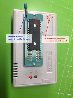
- Insert your EEPROM into the programmer in the correct orientation (check the small notch) and lock it in place with the small lever
- Program the EEPROM (« Device »-> « Program »).
- Attach a small label to the top of the EEPROM with the reference (LO-0, LO-1, etc.). This will save you from testing all possible combinations when the Atari doesn't start.😁
- Repeat the process from step 5 for the following EEPROMs.


Mac or Linux
The software provided with the programmer is only available for Windows. However, an open-source alternative is available on Linux and macOS: minipro (https://gitlab.com/DavidGriffith/minipro/).
- Install « minipro » (see the GitLab page for instructions).
- Open a Terminal and navigate to the directory containing your TOS images to be flashed.
- Connect the programmer to your machine.
- Verify that your programmer is detected:
minipro -k
- Insert your EEPROM into the programmer in the correct orientation (check the small notch) and lock it in place with the small lever (see picture)
- (Optional) Verify that the EEPROM is properly inserted and recognized. Replace <EEPROM MODEL> with the one you have chosen, such as AT27C256, SST39SF010, etc.:
# minipro -p <EEPROM MODEL> -D
# minipro -p <EEPROM MODEL> -z
- Program your EEPROM:
# minipro -p <EEPROM MODEL> -w <TOS IMAGE TO FLASH> -s
- The "-s" option allows you to skip file size verification. In the case of a 6-chip version, this is not necessary, as our 6 images are indeed 32KB in size, which matches the size of an AT27C256. For a 2-chip version, TOS 1.6 or 2.06 is indeed 128KB in size, matching an SST39SF010. However, for a TOS 1.02, 1.04, or other 192KB TOS versions, each file is 96KB, which is smaller than the 128KB of an SST39SF010. This is not a problem; the remaining space will not be used, but you need to force minipro, which thinks it's an error
- Remove the EEPROM and attach a small label to the top with the reference (LO-0, LO-1, etc.). This will save you from testing all possible combinations when the Atari doesn't start. 😁
- Repeat the process from step 5 for the following EEPROMs.
nstalling the EEPROMs in a 6-chip version (STF) or 2-chip version (STE)
Follow the detailed instructions in part 2 of this tutorial, here
Installing the EEPROMs in a 2-chip version in ST/STF/Mega ST
((I assume your machine is ready to receive only 2 chips; if not, the modification is explained in part 2 of this tutorial.) You can quickly see that it doesn't fit! Your machine has 28-pin sockets, and your chips have 32 pins. You'll need to "modify" the chips to make them fit, but it's not too complicated.
First, let's look at the pinout of a 28-pin 1Mb chip and a 32-pin 1Mb chip :

- Most of the pins are the same, which is good news.
- On the SST39SF010, pin A16 is in the top-left corner, whereas on the original ROM, it's on the right side.
- The SST39SF010 has an "OE#" pin where the original ROM has A16.
- The SST39SF010 has an unused pin (NC) where the original ROM receives its +5V, which is good.
- The +5V of the SST is "floating," 3 pins too high.
- The SST has an additional signal, "WE#," in the top-right corner.
If we look at each PIN:
- The OE# pin of the SST needs to be gently lifted and soldered to VSS with a small wire. This is the "Output Enable" signal, and we want the ROM to send data when requested. Since this is a signal that is active "low," it means it must be connected to ground to be operational. So, solder it to VSS.
- VDD and WE#: WE# stands for Write Enable, which allows programming this chip. Since we want to use it as a ROM, we must ensure that this signal is never active. Also, it's an active "low" signal, meaning it must be connected to +5V to be inactive. This works well since the next pin is +5V. A small solder blob should suffice between pins 31 and 32. As we also need to connect all of this to the original +5V, found on pin 30, you can simply create a new solder blob to connect the 3 pins together, with pin 30 bringing +5V to the other two.
- A16: Here, there are two options, but in any case, you need to solder a wire to the A16 pin of the SST. Then, you have the choice of slipping the other end of the stripped wire into the socket, under the OE# pin that you lifted in step 1. Another, simpler option: the empty socket next to it can be used; simply slip the other end of the wire into pin 22 of the empty socket, and you have A16.
- Repeat the same operation for the second chip, and you have a working TOS.
The diagram shows these modifications. In the photos, you can see a modified chip; I cut the bottom of the pins that don't fit into the socket, but this is not necessary.


All that's left is to place your new chips in the machine and test that everything works. If not, check your connections, make sure you've placed the HI chip in the HI socket and the LO chip in the LO socket. And make sure that the pins "sticking out" of the socket are on the side of the notch. In this regard, never rely on the socket's notch but on the one engraved on the motherboard. Atari had the bad habit of soldering some sockets upside down (see photo).

You should now have a machine with a "Handmade" TOS. In the next part, we will look at how to have multiple TOS versions in the same machine and how to run TOS 2.06 on an ST/STF/Mega ST.
Back to Hardware hacks