Basic Troubleshooting - Identifying components
When we are starting to troubleshoot, we are faced with a board or PCB (Printed Circuit Board) that contains many components, all of which are necessary for the completion of the electronic circuits which make up our computer.
Understanding the function of these components is essential to our understanding of what makes up these circuits, and what we can expect that circuit to do, but of course identifying these components is equally important, because if we are asked to check the resistance of a resistor, but we check a diode instead, then we'll get the wrong result.
What should be remembered (If you have read the section on Datasheets) is that all discrete components will have a datasheet that you can download. It will help you identify these components, understand their function and tell you everything you need to know about them.
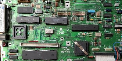
With that in mind, we'll take a look at a section of Mega ST mainboard as below and identify the components:
Starting off with the chips, we can identify a number here outlined in red:
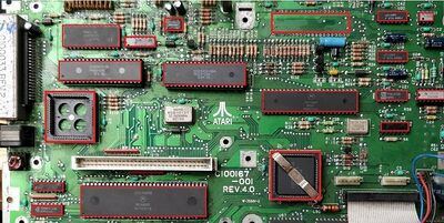
These are generally marked with a "U" on circuit boards. Item 3 on this image is marked as U26 for example. The number simply represents a location on the circuit board
These are the most important components on the board. The largest chip is the CPU, a Motorola 68000. The other larger chips are custom Atari chips, and the smaller chips are a mixture of chips performing many different functions, many of which belong to the 74LS family of logic chips. All can be identified by the number printed on top, and with the exception of the Atari chips, you will be able to find datasheets for all of these.
Also important with chips is identifying which pin is number 1. Obviously this can be done using a datasheet, but it can also be done at a glance as below:
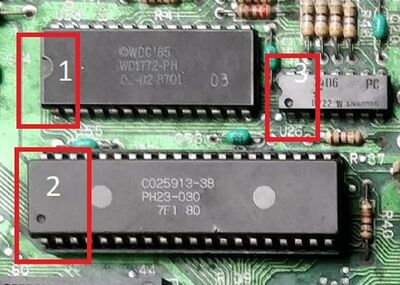
1. Chip orientation is identified by a notch at one end, and pin 1 is to the left.
2. Chip orientation is identified by a dimple next to pin1.
3. The chip has both methods 1 and 2 to identify the location of pin1.
PLCC packages, being square, have different ways to identify pin 1.
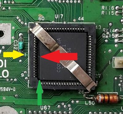
1. Identified by the red arrow, there is a dimple at pin1.
2. Identified by the green arrow, the dimple is on a beveled edge on the chip. The chip will only have one beveled edge. It will also have a single beveled corner that will help orient it in the socket. Be aware it is still possible to fit chips the wrong way!
3. You will also need to identify pin 1 of the socket. The yellow arrow indicates a "1" silkscreened onto the PCB indicating the edge and approximate location of pin1. You will also often see the pin numbers at the corner of each socket, as is the case here. Finally, but the least visible, is that the top edge of the socket will have either a small arrow or a dimple indicating pin1.
The most prolific component on the board is the resistor, as can be seen here:
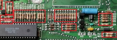
Resistors are generally marked as "R" and a number, like for the chips. The number simply represents a location on the circuit board and not the value of the resistor.
Resistors do exactly what their name suggests, and restrict the flow of electricity. The amount the flow is restricted depends on the value of the resistor and is measured in ohms and represented by the Greek Omega symbol.
Their size is an indicator of how much power in watts they can absorb based on the equation watts = volts x amps. Typically on a TTL logic computer like the Atari ST, where voltages are realistically no more than 5v, resistors are unlikely to be more than 1/4 or 1/2 watt.
Although in the bulk of these resistor groups you can see they are all of a base brown colour, it is also possible to see them in other colours, however they do have one thing in common which is a colour band system that indicates the value.
It is beyond the scope of this article to identify all the different values, since there are online resistor calculators and apps for mobile phones that allow you to do this.
The key thing to remember is which end to read the value from. My advice is that if you can see a gold or silver band, hold that end of the resistor in your right hand and read the colour bands from left to right. The bands will then be in the correct order and you can use a guide or app to correctly decide the value. The gold/silver band indicates the resistor tolerance i.e. how much it can vary up or down from its base value.
If you can't see a gold or silver band, then it's difficult to decide which end to read from, so in this case I'd suggest a multimeter set to ohms mode to measure the value of the resistor. This is my preferred method.
We can also see in use resistor packs:
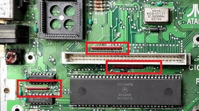
These are generally marked with "RP" on circuit boards, such as RP1 on this image. The number simply represents a location on the circuit board
And these are generally needed where several lines, such as a databus are all in need of a pull up. In other words they need to be forced high or 5v. They work since there are a group of resistors all tied together at one end on a common bus, with pins that allow for connection to multiple data lines. Only a single connection is then needed to pull up all 8 lines to 5v.
The common connection is marked with a dot, and values are also printed onto the side of the pack. Values can be Googled or taken from the datasheet. Alternatively you can measure from the common pin to any of the other pins with a multimeter.
Next come capacitors.
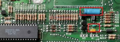
Capacitors are generally marked as "C" and a number. The number simply represents a location on the circuit board and not the value of the capacitor.
Capacitors come in many shapes and sizes, the largest type being electrolytic capacitors as shown here by the large blue cylindrical item. Capacitors store electricity and their value is measured in Farads, or the amount they can store.
They are generally used to help smooth out the peaks and troughs in the voltages found around a computer like the Mega ST.
Most capacitors you'll find in a computer like this have values in either the nanoFarad (nF), picoFarad (pF) or microFarad (uF) ranges.
Electrolytic capacitors are the easiest to identify, since they have a value printed on the side and also usually have a maximum operating voltage indicated. An example might be: 2200uF 16v.
Electrolytic capacitors also then to come in 2 packages:
1. Axial - As per the blue item in the picture, they have a lead at either end.
2. Radial - These have 2 legs extending from the rubber bung in the bottom of the capacitor.
It is important to remember that electrolytic capacitors are polarised, in that they have a positive (+) and negative (-) connection and must only ever be connected correctly, or the component may be destroyed.
Other capacitors, notably Tantalum types, are generally polarised and MUST be connected the correct way around.
Other smaller capacitors, like the yellow and green items shown in the image are not polarised and can be connected either way around without harm.
Identification of capacitors other than electrolytic types depends on their size, type and manufacturer. You may find very small capacitors with a value of 104 printed on them, which would be a .1uF item, whereas an item marked 101 would be 100pF.
There are some which will have the value simply printed on them. Due to this wide variation, like the resistor it is suggested that you look up the value using an app for your phone, or directly on the internet. Like the resistor, it is also possible to get a specialised capacitance meter that will allow you to check the value rather than decipher whichever code the manufacturer is using.
Next lets talk about diodes:
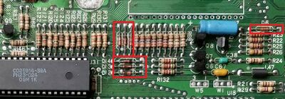
Diodes are generally marked as "D" and a number. The number simply represents a location on the circuit board and not the value of the diode.
Simply put, diodes are a one way valve for electricity. If there is a need to ensure that electricity will flow only one way, then a diode will do it.
On this particular computer, there are many diodes in use, and like resistors and capacitors, there are many different types, including the light emitting diode which we are all familiar with.
These components are also variable in size, dependent on their job, and in this image what we are seeing are small signal type diodes. Diodes also have a polarity, with the cathode (-) side indicated by a band, so must be connected the correct way around. In the case of digital logic circuits, these 'signal' diodes are used as they are particularly suited to low current and high frequency operations, and they are extremely reliable and rarely fail.
Aside from the band, they can be identified by markings on the casing, though due to their size in some applications, a magnifying glass is recommended!!
Again, it is not the place of this article to help you identify specific variations, but rather help you perform a basic ID. To further identify the diode that you have in front of you, a simple Google search or a phone app will get you the rest of the way.
Next are transistors:
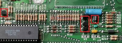
Transistors are generally marked as "Q" and a number. The number simply represents a location on the circuit board and not the value of the transistor.
Transistors are generally used for two purposes:
1. Switching.
2. Amplification.
Transistors generally only come in a package with 3 legs, and whilst they do come in different types depending on the electronic material contained within, they are generally only identifiable by their form/shape.
They normally will be cylindrical in shape, but with a flat portion, onto which is usually stamped/etched/printed the identification number of the part, for example BC107. There is usually a circle with a flat side silk screened onto the circuit board so that a transistor can be placed in the correct orientation for the circuit to work.
If a transistor fails, it is important to note that you may find it's done so catastrophically and is split, rendering it impossible to read the ID code, so this is where the use of schematic diagrams can help you once you know the "Q" number from the circuit board. This will allow you to accurately identify what a component is.
Make sure when replacing transistors that you replace like for like. Some transistors have the same part number, but their characteristics can vary from part to part. For example, a BC337-16 & BC337-40 are from the same family, but have different characteristics like gain. In a power supply, this could cause a catastrophic failure and even a fire. If in doubt, ask an expert here and check the datasheets before doing anything.
Lastly we'll take a look at oscillators and crystals:

Oscillators are generally marked as "OSC" and a number. The number simply represents a location on the circuit board and not the value of the oscillator.
Crystals are generally marked as "Y" and a number. The number simply represents a location on the circuit board and not the value of the crystal.
A crystal is essentially just that, a piece of crystal, and it generally used as a part of an oscillator circuit.
However, it can be the case that synchronising an oscillator work with a specific circuit is difficult to do, so whilst in some cases, such as here, it will work fine, in other cases it won't, so this is where the oscillator comes in, as it is a self contained part that is guaranteed to work at the desired frequency. An oscillator will also most likely contain a crystal as part of it's makeup.
Generally speaking these components rarely fail, since oscillators contain all the components they need inside a hermetically sealed 'can. However it may be the case that the support components for the oscillator circuit that uses the crystal can fail, however it is generally unusual for the crystal itself to fail.
Oscillators generally come with 4 legs, negative, positive, output and a final leg that is just used for support. They are generally identified by the frequency at which they operate, in this case 32.0424Mhz,and a manufacturers part number.
The crystal in this case has a frequency of 2.4576, but doesn't state Mhz or Khz, so datasheets will help again here in conjunction with the part number.
The frequencies delivered here will often be present at various points on the circuit board, and my be modified, such as halved, to be used where needed. The CPU in a Mega ST for example requires 8Mhz connected to the clock pin.
So this is the end of a brief tour of how to identify basic components. Whilst other components, such as inductors, are present on the circuit boards of these old computers, the main parts you'll need to know about are covered above.